Overview
I made this game primarily as a learning exercise to completely design and build a digital circuit using a microchip with in-house parts.
- Players: 2
- Objective: When the display reads "0", players turn on their light switch as quickly as possible. Whichever player turns on their light switch first is the victor.
Rules/Operation
- Turn it on (using the light switch attached to the main board)
- The display should read "0"
- Both players turn on their light switches
- The display should read "1"
- Both players turn off their light switches
- The display counts down "3" "2" "1" and the game begins
- Wait until the display reads "0".
- Players press switches as quickly as possible
- If a player switches their switch before the display reads "0", they lose
- The display will display a lot of numbers very quickly
- The victorous player's number will be displayed
- Continue from step 2
Gameplay
Don't get the wrong impression--the display doesn't go to "0" right after the "3" "2" "1" countdown--this only happens once in a while when all the random conditions are met. The game is completely random and shifts between different "game modes"--counting up and down (by 1 and 2) and random numbers. It can do all of these in a normal or fast speed. It can do these with a certain chance of randomly going to zero, or going to zero after the "game mode" is finished. A random number of game modes are chosen and initialized (randomly) before the game starts. The game modes each can be repeated a certain number of times. The game modes are then iterated over in a random order. Games usually run from 15 seconds to 5 minutes. Some people enjoy the short games lasting 15 second or less--especially me--while others enjoy the wrenching games up to 5 minute long. Entropy is introduced (and used in subsequent calculations) by the time difference between a player turning on the game and flipping a light switch. An example game:
- 3 2 1 go:
- Start from 7 and countdown slowly (a little less than a second)
- Hit 1 and start at 7 another time
- Random numbers! Display 7 of them in fast mode
- Do that 4 times
- Count down by twos slowly
- During the count-down, randomly change the number to 0
Design Overview
The game is built around the 8-bit Freescale MC9S08QG4 microchip. Two pins on the MC9S08QG4 are wired (with pull-down resistors) to two light switches which provide the necessary input from players. Three other pins are wired to the inputs of a 74LS47, driving the display. I was too lazy to wire the extra pin to the display or provide support for a third player. I wrote the firmware for the MC9S08QG4 using the supplied Freescale Codewarrior in C and assembly. An off-track note about Codewarrior: It's not actually suited to editing code. It can't auto-tab correctly and auto-complete isn't functional--not that I needed autocomplete for this project. I usually edited code with jEdit then copied & pasted it to Codewarrior. It's other features like Device Initialization and work-the-first-time-I-plug-it-in are fantastic, though!
Hardware

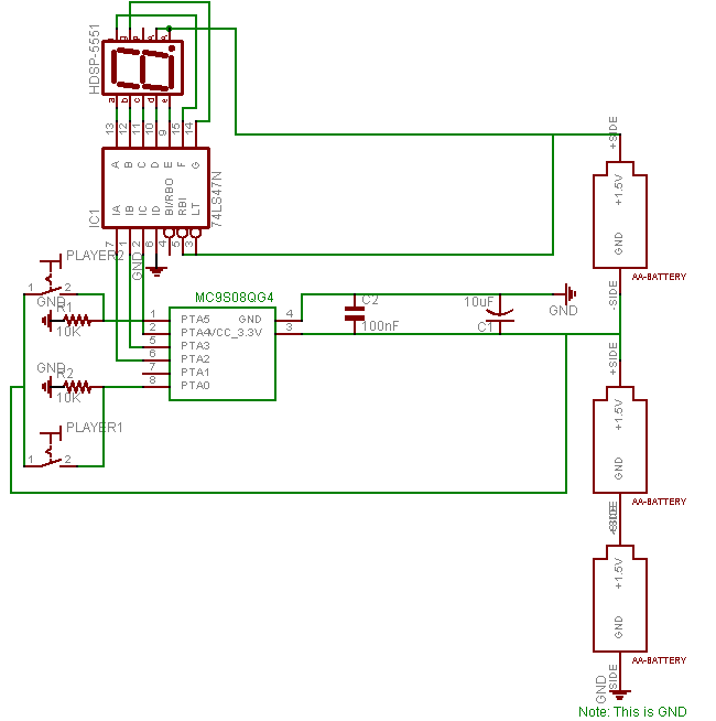
The above circuit diagram and ensuing custom parts library were made with Eagle CAD--the free version. It was made after I actually built, wired, and tested everything--which explains why I forgot the "on" switch. Many people--from hobbyists to industry professionals--make the mistake of designing and reviewing and testing their circuits before building them--well not me!
The circuit revolves around three pieces: the display, the mircochip, and the light switch input.
Microchip
The MC9S08QG4 reads input from the switches via PTA5 and PTA0 and controls the output to the 7-segment display via PTA4,PTA3, and PTA2.
The MC9S08QG4 takes 3.3v for power. I accomodate this difference from the 5 volt devices (74LS47 and HDSP-5551 display) by only using two of the three AA batteries (1.5v + 1.5v = 3v = ~3.3v). A 100nF bypass capacitor and a 10uF bulk capacitor protect the MC9S08QG4 from fluxuations in power.
Display
I use a 74LS47 display driver to convert the binary input from the MC9S08QG4 into the decimal output for the 7-segment display. The 74LS47 does have its own 100nF bypass capacitor not shown on the circuit diagram. I use an HDSP-5551 common anode 7-segment display. The choice for the HDSP-5551 in particular was heavily biased--I already had one. I use 390 ohm resistors between the display and the 74LS47 because I had a large amount of 390 ohm resistors lying around. Could I do better? I think the displays draw around 24mA of current (No I'm not going to check the real value). 5.5 volts / 24mA = 229.2 ohms--yes I could do better.
Switches
The switches are the standard cheap-o light switches (purchased at Home Depot). They are wired with a 10k pull-down resistor--the pins will float otherwise--to the inputs of the microchip. Debouncing enthusiasts seeking such will be displeased--there is no need to debounce these switches. They are fairly large swithes and not connected to an interrupt-enabled pin. Plus, I do not want to wait for any debouncing business (cap charging or SR-latch computing) to occur, as this is a reflex game.
Underside
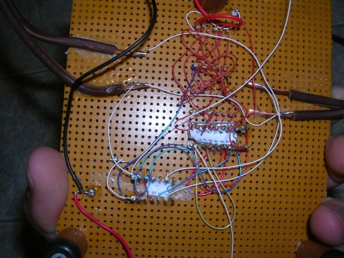
This picture reveals shoddy wire-wrapping, poor soldering, and liberal use of super glue. The wire wrapping has no actual color scheme.

Firmware
I used the Device Initializer to generate most of the initialization code. I disabled the BKGND pin so that I could use it as an output-only pin. I only optimized the parts for which I deeply cared, such as the routine to select a winner.
I think there are a few existing bugs, like setting the TPM timer before setting the MOD count. I do some other bad things--like return a value that I never use. I'm not particularly proud of the prand_weighted function.
The actual gameplay code (Which happens after the "3" "2" "1" countdown) is the most interesting. The game is described by an array of structs which contain the "game modes" of the game, among other things. The array of structs is populated before gameplay begins with random data (I use the input from the switch as a source of entropy). The key element of the structures is a function pointer to a "game mode"--a function that is called every game loop. A good example of a "game mode" is countdown, which decrements the number on the display by 1 every game loop. The array of structs is processed in a random order.
Here is the Codewarrior project (source code) in its entirety: Reflex game project.
Microchip Notes
The game is built around the 8-bit Freescale MC9S08QG4 microchip. I obtained both the microchip and programmer (USBSPYDER) through a conference-goer free of charge. The MC9S08QG4 came in the 8-pin DIP package, which was great for me.
Conclusions
What I like
- I can take it anywhere
- It runs on AA batteries
- It's actually fun
What I don't like
- It's rather fragile
- It has no case
- Only 2 players
- Some of the games simply last too long for me--but others enjoy them.
Things I learned
- If you don't own superglue, you better get some right now! The faster-drying the better
- Don't worry about supergluing your hands and such--it washes away eventually
- Proper lighting is a huge asset
- Buying a static protection wrist strap is worth the price if you are working with CMOS components. I bought one for $11 at Radioshack.
- Instead of taking the MC9S08QG4 in and out of the programmer directly, I put in it in sturdy 8-pin DIP package. That way, I didn't have to worry about bent pins.
Is it fun?
I played with some family members and we found it to be somewhat addictive. In about two days over 50 rounds were played. I was very suprised--from the onset of the project I did not believe it would be enjoyable to play.
Downloads
- Codewarrior Project with source code for MC9S08QG4
- Eagle cad part library for MC9S08QG4 and AA batteries - made custom by me
- Eagle cad schematic for the reflex game
- Using the wire wrapping ID tags (PDF) provided by Peter Mathys from the University of Colorado prevented mistakes in wire wrapping. The file is not hosted at ForrestHeller.com and it looks copyrighted.
Parts list
- 1 MC9S08QG4 - $1.56 from Digi-Key
- 1 Perf board
- 1 74LS47
- 3 light single-pole switches
- Wire wrap
- 3 AA batteries
- 1 4-AA battery case (I only needed a 3 battery case, though)
- 7 360 Ohm resistors
- 2 100nF capacitors
- 1 10uF capacitor
- 30 second fast drying super glue
- 4 14-pin gold-plated DIP socket (2 inappropriately on 7-segment display)
- 1 18-pin gold-plated DIP socket